A valid file is not yet a viable part
Finding a downloadable model is only the beginning. A file can describe three-dimensional geometry and still fail to provide what another person needs to make a part that fits their object or withstands its intended use. Reuse requires more than access to the model: it also depends on how the part will be manufactured, on the printer and material, and on what has been checked after printing. It is therefore useful to separate three questions: can the file be opened and interpreted; can it be produced using a particular process; and does the result perform a defined function? A yes to the first question does not answer the other two. Treating these questions separately helps avoid mistaking a shareable file for a validated replacement part.
Before downloading or publishing a design, identify the problem it is intended to solve. A decorative support, an unloaded cover and a part that transmits force do not require the same level of verification. It also matters whether the replacement is intended to reproduce an original part exactly, is an adaptation, or is merely a temporary solution. These distinctions should appear in the description rather than being left implicit in the filename. In particular, it is unwise to call a part “compatible” if compatibility has only been inferred from an image or general dimensions. A useful description makes clear what is known, what was actually tested and what remains uncertain, so that another person can judge whether the design is suitable for their particular object and use.
What can be checked in the geometry before printing
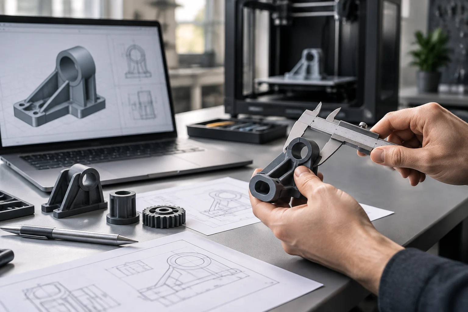
Reviewing a model can reveal obvious problems, although it cannot prove how the finished part will work. Check whether the geometry is complete, whether its surfaces and volumes form a coherent part, and whether its principal dimensions correspond to those of the component it is meant to replace. Inspect contact areas as well: holes, slots, tabs, joints, flat surfaces and any feature that must line up with another part. If the model consists of several pieces, clarify whether they are printed together or separately and whether supports or later assembly are needed. These are checks of the digital design; they are not the same as physically inspecting the replacement part. A file that opens cleanly may still be incomplete for its intended application, while a geometrically plausible model may need further preparation before it can be manufactured.
Dimensions in context
Dimensions are much more useful when the description says what was measured and how. An external measurement, for example, does not by itself describe the clearance of a joint or the depth of a recess. If you publish a drawing, a dimensioned screenshot or a parametric file, state the units and identify the functional dimensions. It also helps to distinguish measurements taken from the original object from design decisions. A tolerance should not be presented as a universal figure: whether it is appropriate depends on the geometry, process and application. The file alone does not necessarily reveal which surfaces are critical to fit. That is why a short explanation of the intended interfaces can be as important as the model itself. It gives the person reusing the design a way to connect the digital geometry to the physical component it is supposed to meet.
A design may contain features that are difficult to manufacture, such as thin walls, small holes, overhangs or abrupt changes in cross-section. Whether they can be reproduced depends, among other things, on the technology and the selected settings. A useful review therefore does not stop at opening the model in print-preparation software: it also considers how the geometry is converted into paths or layers and whether that preparation produces a shape appropriate for the intended use. Prusa’s guide to designing for 3D printing treats modelling constraints as issues connected to manufacturing, not as an automatic guarantee that every printer can reproduce the result. The distinction matters when a file is shared beyond the equipment on which it was originally prepared. (Source: Prusa Knowledge Base).
The machine, material and orientation change the result
The same geometry does not become the same part under every set of conditions. Changing the printer, material, process or settings can alter the dimensions of the result and how it responds under load. With a filament printer, for example, the file prepared for manufacture incorporates decisions such as orientation and extrusion settings; other additive-manufacturing processes have their own variables. Orientation can affect both the need for supports and the arrangement of layers. As a result, the label “printable” is imprecise unless it says, at a minimum, under what conditions the design has been checked. Dassault Systèmes’ general guide presents 3D printing as a group of processes, but the documentation available for this part does not allow a universal setting to be inferred for all of them. A claim about one prepared example should not be silently extended to equipment or processes that have not been tested. (Source: Dassault Systèmes).
Document the preparation, not just the model
To help someone else interpret a result, record the type of process and, where relevant, the printer and material used. Add the recommended orientation, file version and manufacturing settings relevant to the part. The publication does not have to become a complete manual for a particular machine, but it should distinguish what belongs to the design from what belongs to a specific preparation. If you share a slicing profile, identify it as a reference configuration, not as proof that it will work unchanged on different equipment. Calibration should not be hidden behind a generic compatibility statement either: Prusa’s documentation, for example, describes calibration of the extrusion multiplier as an adjustment task. This is a reminder that a model and the settings used to produce it are different pieces of information, both of which may matter when comparing outcomes. (Source: Prusa Knowledge Base).
A simple way to prevent misunderstandings is to label each item of information as measured, specified or estimated. Reserve “measured” for an observation that was actually recorded; “specified” can describe a dimension in the model; “estimated” indicates that it has not yet been confirmed on a physical part. Preserve the distinction between the design’s nominal value and the dimension observed on a manufactured example as well. If you do not know what process the person downloading the file will use, say so explicitly. That limitation does not make the model useless. It lets the person reusing it decide whether to adjust the geometry or make a preliminary test, rather than relying on an overly broad promise. Clear labels also make it easier to update a design later without confusing an assumption with a recorded result.
Tolerances, fit and functional testing
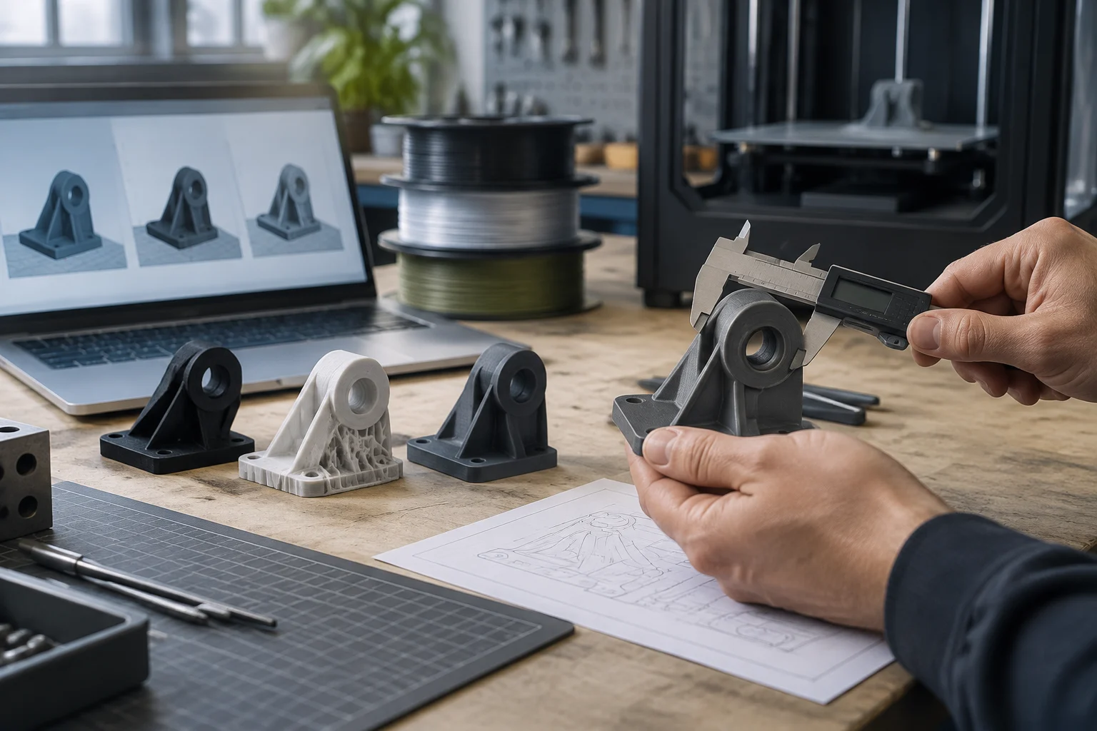
Nominal dimensions describe the design, but a physical part may not reproduce them exactly. To assess a fit, giving a single measurement is not enough: explain which parts interact, where the measurement is taken and what behaviour is expected. Should the part enter with clearance, be held by friction, rotate without sticking, or align with a screw? The answer determines which surfaces and dimensions matter. If the necessary tolerance in the original object is unknown, avoid inventing a figure that merely looks precise. Instead, explain the uncertainty and propose how to check it with a test part or by measuring the receiving component. This keeps the description useful without claiming a level of accuracy that has not been demonstrated.
Prusa’s design documentation offers recommendations on modelling with the limitations of printing in mind, while its calibration guide shows that extrusion settings can be adjusted. Neither reference establishes a universal tolerance for every replacement part, machine and material. This is an important limit: a recommendation for one technology or configuration should not be presented as a specification for all printers. The available references support attention to manufacturing constraints and adjustment, not a single tolerance value that can be applied indiscriminately. (Sources: designing for 3D printing and extrusion multiplier calibration).
From fit check to use test
An initial fit test could involve manufacturing a section, gauge or simplified version that allows a critical dimension to be checked before printing the complete part. Then verify that the component enters, aligns or moves as expected for its function. If the part bears a load, must withstand heat, gets wet, vibrates or is subject to wear, a fit check does not demonstrate that it meets those demands. Tests should correspond to the stated use and should be conducted in a way that does not confuse one example with general validation for every printer or batch of material. Avoid saying that a part is “strong” unless you specify what was observed and under what conditions. A report of a concrete test is valuable precisely because it identifies its scope, rather than implying that all possible conditions have been covered.
How to share a design with reusable information
A responsible publication helps other people understand what they are receiving, repeat the checks and recognise the limitations. Alongside the file, include a description of its function, critical dimensions, design version and the process used to manufacture the example shown. If you provide photographs, make sure they show the fit areas, not just the overall shape. Explain whether the part was tested on the original object, on a reproduction or only in a trial assembly. Evidence from a specific test should be described as specific: it does not become a guarantee of compatibility with differently manufactured objects. Clear reporting helps readers distinguish demonstrated results from expectations and decide what further checks their own application requires.
Short publication checklist
- State which component the design replaces and which versions or measurements are known.
- Attach the model and, where appropriate, a dimensioned drawing with units and functional dimensions.
- Describe the process, material, orientation and relevant settings for the example that was checked.
- Explain what test was carried out: dimensional inspection, fit, movement or use test.
- Distinguish observed results from recommendations and identify limitations that remain open.
- Keep a version identifier so that corrections are not confused with the previous file.
Repositories can make models easier to access, but the presence of a file on a platform is not, by itself, technical certification. Read the description and look for verifiable details about dimensions, process and testing. If those details are missing, it is not possible to conclude that the design is defective; there simply is not enough evidence to say that its reusability has been demonstrated. In that situation, the prudent approach is to treat it as a starting point and check the interfaces against the specific object before relying on it for an important function. Greater caution is appropriate for safety-related parts or parts subject to significant loads: this article does not replace a specific technical assessment and does not provide product certification.