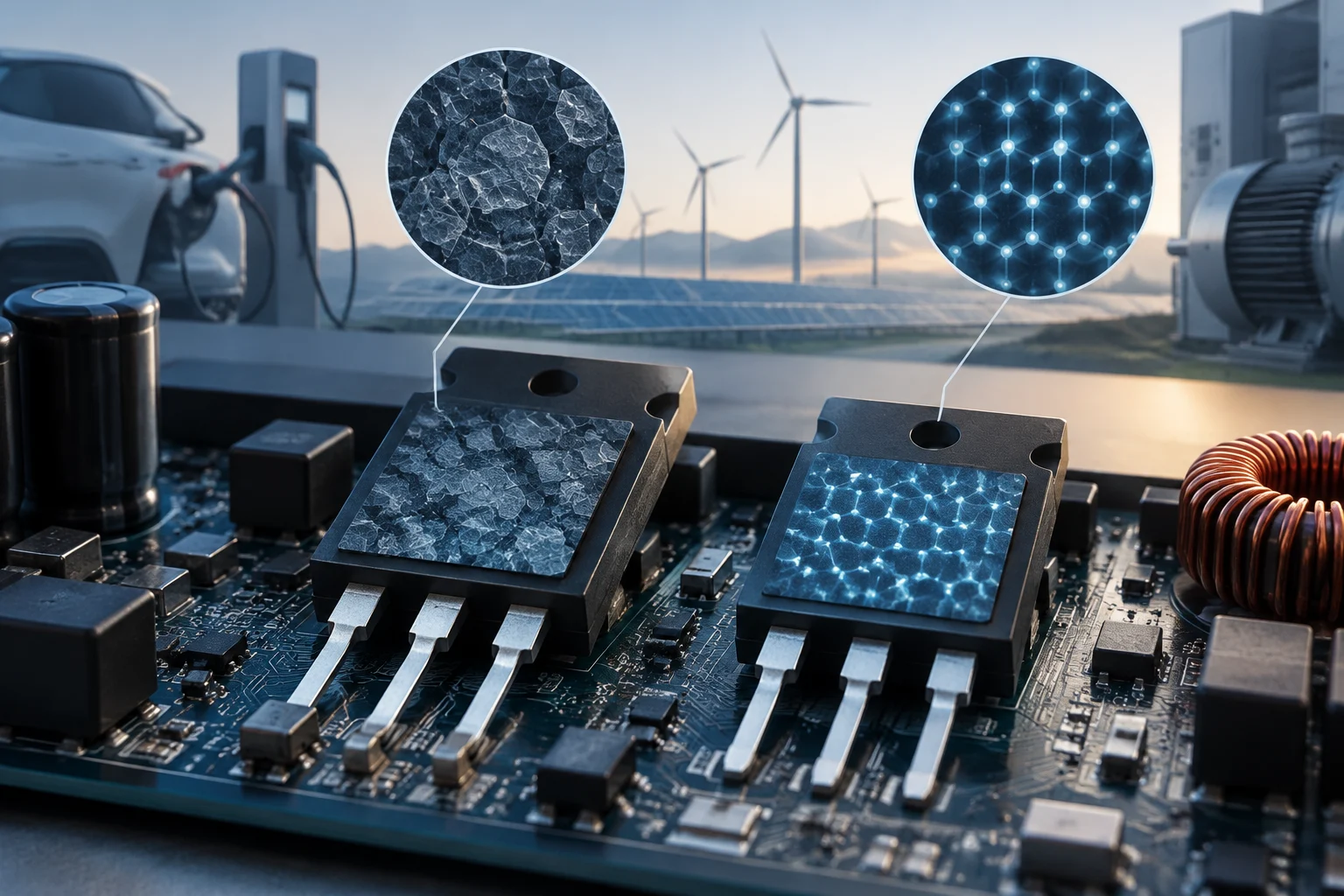
What makes a power semiconductor different
Power semiconductors control or convert electrical energy: they can act as switches in a power supply, an inverter or a propulsion system. They should not be confused with logic circuits, whose main purpose is to process signals and data. This distinction describes how a device is used; it is not an absolute boundary between component families. A power system can also incorporate digital control and signal circuits.
The practical issue is losses. When a transistor conducts, it dissipates energy; it also dissipates energy during transitions between the on and off states. That energy ultimately becomes heat and affects cooling, size and the performance of the complete assembly. For this reason, the label “power semiconductor” does not by itself reveal the efficiency of a charger or a vehicle: the way the device is integrated and the conditions under which it operates matter.
Silicon, SiC and GaN: differences, not a podium
Silicon (Si) remains a widely used option. Silicon carbide (SiC) and gallium nitride (GaN) belong to the group known as wide-bandgap semiconductors, whose properties can be advantageous in designs that need to withstand high voltages or switch rapidly. Technical comparisons describe design opportunities, not the universal superiority of one material over another.
SiC is associated with high-voltage power-conversion applications, including systems linked to electric vehicles. GaN appears in compact, fast-switching conversion designs. However, the ability to operate at a particular temperature does not mean that the finished product will always operate at that temperature or that it eliminates the need for cooling. The package, control circuit, thermal dissipation and operating conditions all affect the result.
A useful comparison is between specific components and designs, not between material names in isolation. A well-chosen Si transistor may be more suitable than a SiC or GaN alternative for a particular application because of cost, availability, voltage, frequency or design simplicity. The available sources provide general context, but not a like-for-like comparison of parts tested under identical conditions; they therefore do not establish a quantitative winner.
What RDS(on), VDS and Id tell you
In a MOSFET, RDS(on) is the resistance between drain and source when the device is on, under the conditions stated in the datasheet. In general, lower resistance can reduce conduction losses. However, the published value usually applies at a specified junction temperature, gate-drive voltage and current. If those conditions change, the effective resistance may change too.
VDS is the voltage between drain and source. A datasheet typically gives the maximum limit that the component can block under particular conditions; this is not an automatic recommendation for the equipment’s operating voltage. Id describes drain current according to the manufacturer’s definitions and conditions. These limits require design margin: choosing a rated voltage only slightly above the expected value does not prove that the circuit can withstand real transients or variations.
For an initial review, check the following: 1) that the voltage and current limits suit the application; 2) that RDS(on) is compared under equivalent conditions; 3) that curves for temperature and gate drive are reviewed; and 4) that the energy or charge associated with switching is checked along with the test conditions. A single figure cannot replace electrical and thermal analysis of the circuit.
Switching losses and system efficiency
During switching, the transistor passes through intervals in which voltage and current overlap. This behavior produces losses, whose significance depends on switching frequency and converter topology. A datasheet may include parameters that help estimate them, such as gate charge or switching energies, but applying those values requires knowledge of the circuit and measurement conditions. It is not valid to infer equipment efficiency solely from RDS(on) or the chip material.
The diode or reverse-conduction path, magnetic components, capacitors, controller, connections and cooling also matter. Reducing transistor losses may enable a more efficient or compact design, but the result depends on the remaining losses and on how heat is distributed. Efficiency is a property of the system under a defined test condition, not an attribute that can be transferred directly from one component to the entire product.
In an electric vehicle, for example, power electronics are part of a chain that includes the battery, inverter, motor and controls. A semiconductor may help limit losses, but vehicle range and energy consumption depend on many other factors. The same is true of consumer power supplies: an advanced component does not, on its own, certify the efficiency of the completed power supply.
Applications and choosing according to the problem
SiC and GaN are researched and used in different energy-conversion systems; applications described for SiC include power electronics in electric vehicles. Suitability depends on requirements such as bus voltage, current, switching frequency, temperature, space, cost and cooling strategy. A market trend or an application example should not be turned into a purchasing rule.
To choose a device, start by defining the operating point and system limits, rather than searching for the newest material. Then compare official datasheets for candidate devices using the same criteria for temperature, gate voltage and measurement configuration. If comparable data are unavailable, note the difference instead of filling gaps with figures from secondary articles or values for other models.
In a compact power supply, total volume and frequency may be important; in a higher-voltage inverter, blocking capability, losses and thermal management may be decisive. These are design considerations, not guarantees: selection must be validated in the target circuit, with attention also paid to protection, electromagnetic compatibility, reliability and applicable safety requirements.
Standards, testing and what a datasheet proves
A manufacturer’s datasheet documents component parameters and test conditions. It is not equivalent to an energy-efficiency certification for the finished device. General regulatory pages about efficiency, in turn, are not enough to attribute a specific requirement to every transistor or to claim that SiC or GaN carry a universal energy certification. The applicable framework depends on product type, market and use.
When reviewing a declaration of conformity or a label, identify the complete product, the market, the organization or program supporting it, and the test method. Check that the model number matches exactly and that the documentation applies to the relevant category. If the reference concerns only a semiconductor property, it does not demonstrate that the charger, power supply or vehicle meets an efficiency level.
The evidence gathered for this guide makes it possible to explain how to read parameters and describe general differences between materials, but it does not provide comparable official datasheets for specific models or a specific product standard applicable to every example. This limitation prevents publication of a quantitative table of efficiencies or thresholds. For an engineering decision, consult current manufacturer documentation and the regulatory requirements relevant to the finished product.