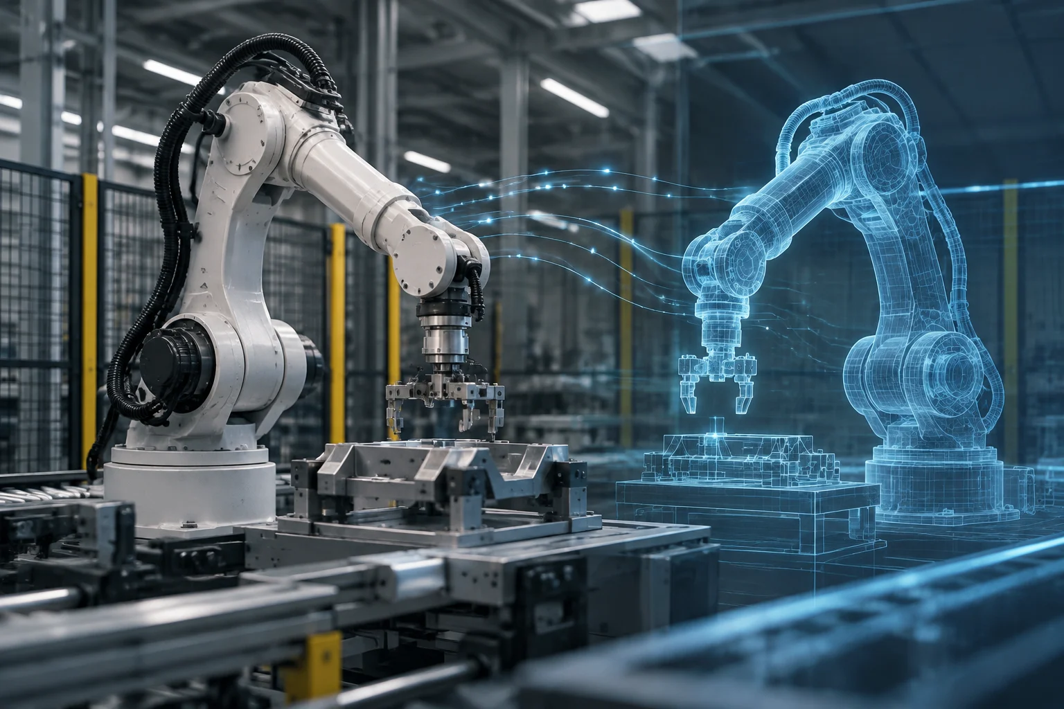
It is not enough for the robot to appear on screen
A three-dimensional representation of an industrial arm can help design a cell, check reach, or prepare a trajectory. That alone does not demonstrate that a digital twin exists for the equipment operating in the factory. The useful question is not whether the model “looks real,” but what verifiable relationship it maintains with a specific physical robot and what information flows between the two. A convincing image may be a useful design aid, yet it cannot by itself establish a live connection, an accurate representation, or an ongoing exchange of information.
It helps to distinguish three things that are often blended together in commercial presentations. In this guide, simulation means calculating or representing a system’s behavior under assumptions; a digital model means describing elements and relationships; and a digital twin means a representation whose relationship to a physical entity and whose data exchanges can be documented. This is a practical distinction for evaluating proposals, not a standards-based definition. The scope needs to be made explicit: what is represented, which information is exchanged, and what is outside the representation. A supplier’s use of the term alone does not settle those questions.
The distinction does not depend on one fixed amount of data per second. A disconnected simulation can be technically sophisticated and useful, but it does not support a claim that it is following the current state of a machine. Conversely, a very limited data connection does not prove that the model faithfully reproduces movements, tools, loads, or the process. The scope should be expressed in concrete, testable terms rather than through the isolated use of the phrase “digital twin.” A buyer can therefore ask what state is actually represented, how that state is obtained, and which conclusions the model is meant to support. Those questions make it easier to compare unlike proposals without treating visual realism as evidence of an operational connection.
The first piece of evidence: identify the asset and the relationship
Before discussing synchronization, a proposal should identify which robot or assembly it represents. Is it one physical unit in a particular cell, a family of equipment, or a generic catalogue robot? It is also important to define whether the digital object includes only the manipulator or also the controller, tool, sensors, workpiece, peripheral devices, and process. Without that perimeter, two parties can use the word “twin” while referring to different things. A clear asset description prevents an attractive demonstration of a generic robot from being mistaken for a representation of the machine actually installed at a site.
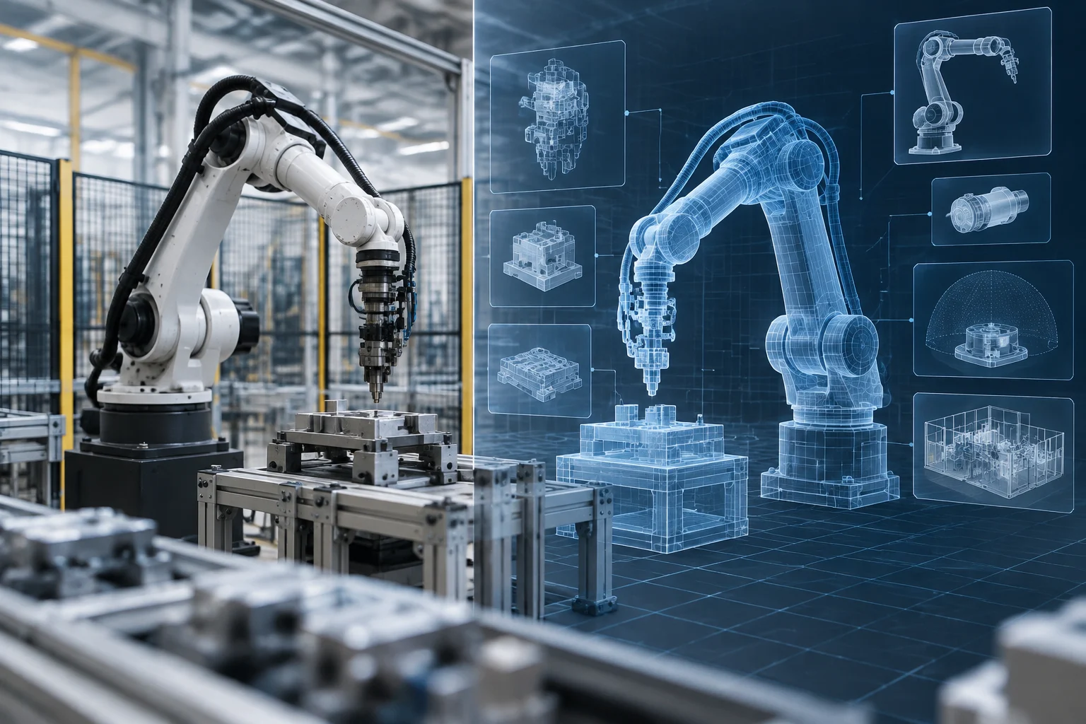
To make the definition practical, ask the supplier to describe the physical asset, digital components, data sources, exchange points, and the parties responsible for each connection. An architecture diagram can clarify which parts are included and which are out of scope. This documentation does not certify that a particular implementation is connected or validated. Its purpose is to make the scope explicit and allow specific, testable questions about the relationship between equipment and representation. The diagram should be understandable enough to trace where relevant information originates and where it goes, without implying that a drawn interface has necessarily been implemented or tested.
Identification should make it possible to track the correspondence between model and equipment throughout the project lifecycle. During a demonstration, for example, the supplier can explain whether parameters come from the controller’s actual configuration, an initial import, or a standard template. These are different situations: a copied configuration can be a good starting point, but it does not establish that the model follows subsequent changes to the robot or its environment. That distinction should appear in the documentation. It is also useful to establish who records configuration changes and how the model is reconciled with them, rather than assuming that an initial match persists indefinitely.
What synchronization means: data, direction, and delay
The word synchronization needs an operational definition. For each relevant datum, specify its source, destination, update frequency or trigger, timestamp, and behavior when communication is lost. Axis position, execution state, alarms, and the active task are examples of information that might be exchanged; it should not be assumed that a particular implementation receives all of them. Evidence should show which signals are actually used and how they are linked to model variables. A signal list is more useful when it identifies units and makes clear whether a value is measured, calculated, or simply configured. That level of detail lets a reviewer distinguish a live observation from a static parameter copied into a model.
The direction of the flow matters too. Reading data from the controller into the model can update a representation, but it is not the same as sending commands back to the equipment. If the system can write setpoints or modify programs, the proposal should specify permissions, limits, and operational responsibilities. Monitoring, scenario calculation, and control should not be confused: they are distinct capabilities, and the level of risk changes with each one. A demonstration should state whether information flows one way or both ways and whether any write function is enabled in the environment being shown.
Latency cannot be summed up by saying “real time.” The measured update interval, the delay each intended use can tolerate, and the way the system detects that a screen is displaying old information all need to be understood. A log with timestamps, packet losses or interruptions, and connection recovery is more informative than a smooth animation. Technical documentation can guide a review of what to examine in an exchange; it does not, by itself, prove that a particular product meets a particular latency. If the claimed use depends on freshness, the evidence should relate the observed delay to that use, rather than presenting a general label as a measurement.
What the model can represent and how to check it
A model can describe geometry, kinematics, joint limits, tooling, payload, work areas, and cell components. But the appearance of those data in a scene does not show whether they were measured, imported from documentation, or estimated. For each relevant element, a demonstration should state its provenance, version, and update method. If the tool or workpiece changes, it should also be clear whether the model is modified and who validates that change. A model may be useful even when some elements are approximate, provided the approximation and its implications are not concealed.
Validation requires comparing virtual behavior with observations of the physical system under stated conditions. Tests might examine trajectories, reachable positions, interference, or process states, while specifying which quantity is compared and what tolerance applies. Conclusions must be limited to the conditions tested: a trajectory matching in one configuration does not automatically establish accuracy at every speed, payload, tool, and operating state. The comparison should identify the physical reference and the model version, so that the result can be repeated or meaningfully reviewed later.
A useful validation record identifies the model and program versions, robot configuration, test conditions, reference data, and observed errors. It also distinguishes geometric validation from process validation. Seeing a synchronized animation is not the same as demonstrating motion accuracy, and a simulated alert does not prove predictive capability. When predictions are presented, ask about the prediction horizon, inputs used, and comparison with observed outcomes—not just a persuasive visualization. Evidence should show what was checked, under which configuration, and how differences were assessed. If a test covered only one trajectory, the claim should not quietly expand to other motions, loads, tools, or process conditions.
Uses that can be evaluated, and limits that should not be hidden
A connected model can support tasks such as monitoring states, exploring layout changes, or trying alternatives before applying them on the factory floor. Its usefulness depends on the available data and the fidelity required for the decision. A state display may need less frequent updates than trajectory analysis; deciding on a maintenance intervention calls for specific evidence about the variable one intends to anticipate. No use is proven simply by naming the system. The supplier should link the claimed benefit to the data, model properties, and tests that support that particular task.
Differences between model and machine can arise from changes that were not incorporated, calibration, backlash, deformation, wear, payload, tooling, or process variation. A model does not have to include every physical phenomenon, but it should state its assumptions and the range within which it has been validated. Outside that range, its results may be indicative and should not be presented as confirmed predictions. A clear statement of limits is therefore part of evaluating the model, not evidence that the model is useless. It helps users understand when the representation is suitable for exploration and when additional measurement or validation is needed.
The sources consulted include a Siemens page about industrial digital twins and a technical NVIDIA blog article about robot simulation in industrial facility digital twins. The available material does not provide test results for a specific robot digital-twin implementation. For that reason, this text sets out criteria for evaluating a proposal, not test results for a particular system. This limitation of scope does not support the conclusion that all projects fail or that all connected models are equivalent. The distinction matters: general material can inform questions to ask, but it cannot substitute for evidence from the implementation being assessed.
Checklist for reviewing a demonstration
First ask for a definition of the represented asset and an architecture diagram: physical equipment, model, information sources, interfaces, and system boundaries. Then request a signal table showing source, destination, units, frequency, timestamps, and handling of failures. If the supplier refers to continuous updating or real time, ask for figures and observable logs that support that description. The documentation should make it possible to trace the information path and tell which parts of the exchange were demonstrated, rather than merely proposed.
To assess correspondence between the physical and digital sides, ask which robot and cell properties were incorporated, where they came from, and when they were last updated. Request a reproducible test comparing controller data with the model, together with the error, conditions, and exact configuration. If a particular use is demonstrated, ask for evidence tied to that use: validating geometry is not enough if the claim concerns predictive maintenance or control. The test should match the stated claim closely enough that its results can be interpreted without assuming performance in untested conditions.
Finally, clarify whether the system only observes or can also act on the equipment, what permissions it requires, and what happens during a disconnection. Ask who maintains the model when tools, programs, or components change, how versions are recorded, and which results fall outside the validated scope. A sound answer can acknowledge limits; a vague answer that replaces those details with realistic images or broad promises does not make it possible to distinguish a useful simulation from a connected, verifiable digital twin. A checklist is not a certification, but it helps turn a presentation into concrete questions and requests for evidence.