Additive manufacturing: different ways to 3D print
Additive manufacturing makes an object from a digital design by adding material rather than removing it from a block. Many technologies build a part in layers; the material and the way each layer is formed vary.
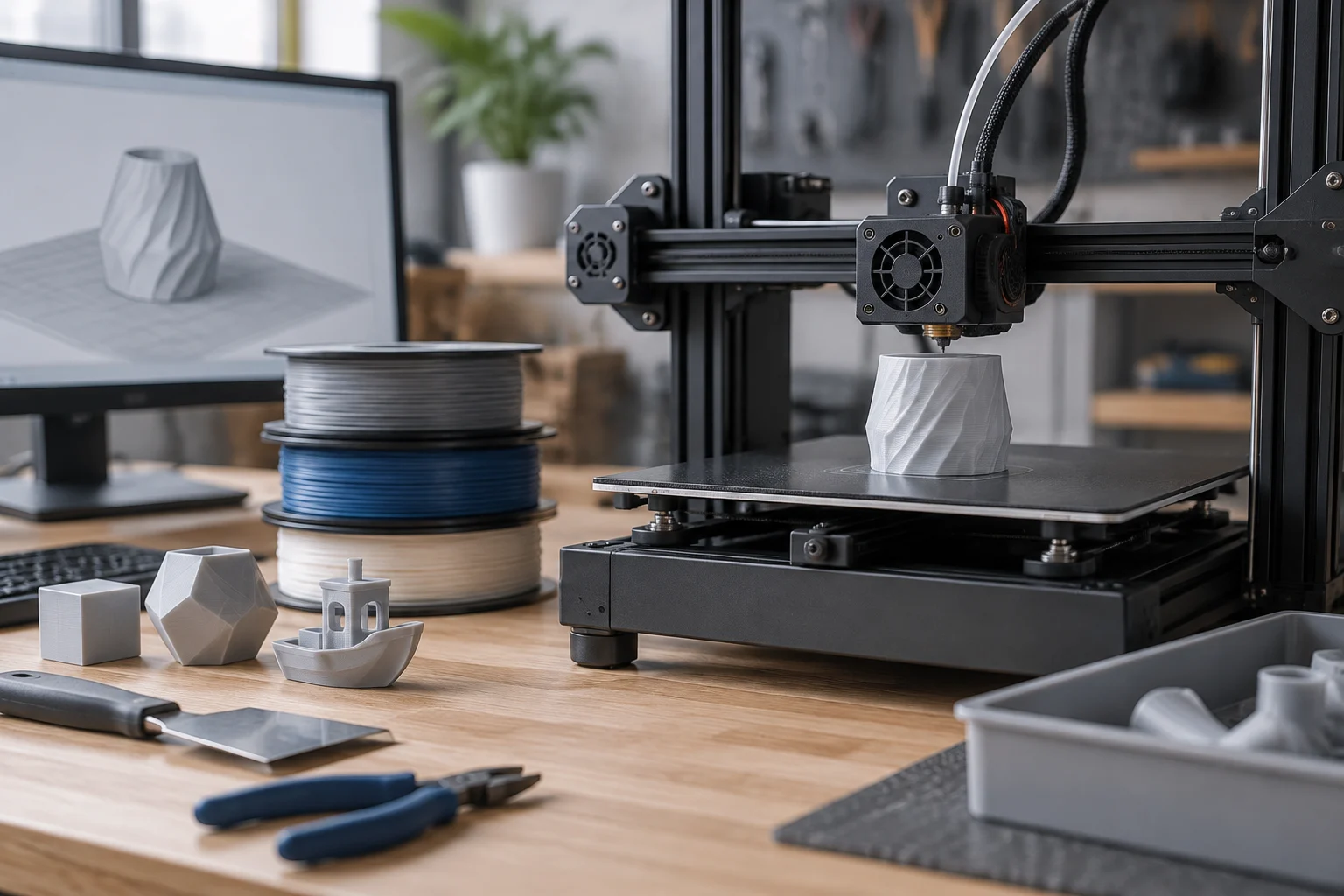
In FDM/FFF, a mechanism feeds thermoplastic filament into a heated nozzle, which deposits the melted material. In SLA, a laser hardens liquid resin; in DLP, a projector exposes an image of each layer; and in MSLA, an LCD screen acts as a mask for the light. SLS uses a laser to sinter powder, usually polymer powder—it does not extrude filament.
These differences matter when preparing a job. FDM/FFF uses filament, while SLA, DLP, and MSLA use photopolymer resin and require appropriate post-processing. SLS builds parts from powder. Materials, settings, and precautions for one technology should not automatically be applied to another.
From a design to printer instructions
A typical workflow is 3D modeling → file → slicer → preview → instructions → printing and post-processing. Modeling means creating or modifying a digital representation of a three-dimensional object. A design can be created with CAD, short for computer-aided design, or be based on a model downloaded with permission. A slicer prepares geometry for a specific printer and profile; Cura and PrusaSlicer are examples. FreeCAD is a CAD tool that can also import and export 3D formats.
File formats are not interchangeable. STL describes a triangular mesh and does not specify a unit of measurement within the file. OBJ also represents mesh geometry. 3MF can package geometry and additional data. A slicer’s 3MF project may also include settings: when opening one, check which printer, material, and profile were imported rather than assuming they suit your own equipment.
STEP is used to exchange CAD geometry, including models with solid geometry and NURBS. The existence of a format does not mean every slicer supports it: compatibility depends on the software and its version. If your workflow involves importing a STEP file, first check that your chosen software supports it.
The slicer divides the model into layers and generates instructions such as G-code. These instructions specify operations and movements for the machine; they are not an editable model. A file prepared for one printer, nozzle, and material may not suit another combination. Check the profile and preview before sending the job.
FDM printer parts and the first layer
On an FDM printer, the extruder is the mechanism that pushes the filament; the hotend heats and melts it, and the nozzle is the outlet through which it is deposited. Nozzle diameter and layer height describe different things: the former relates to the width of lines that can be deposited, while the latter is the vertical thickness of each layer.
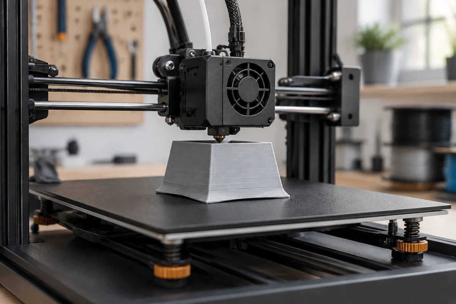
A heated bed is a print base that can be warmed during printing. The print surface is where the part begins and its first layer adheres. In the coordinate system, X and Y position the deposition in a plane, while Z corresponds to height; which component moves depends on the machine’s design. Bed leveling adjusts the distance between the nozzle and the base. Follow the calibration and first-layer adjustment procedure specified for your equipment.
The first layer is a practical checkpoint, not an automatic guarantee that the rest of the job will go well. If filament does not stick or is excessively flattened, the gap between the nozzle and surface may be unsuitable; the condition of the surface, profile, or material may also be a factor. Automatic leveling, when available, does not by itself correct every cause of poor adhesion.
For your first part, follow a straightforward sequence: confirm the printer model and nozzle; select a compatible material and profile; orient the object and enable supports only if needed; slice it and inspect the preview, including the first layer; then start printing according to the equipment instructions.
Filaments and settings that depend on the material
PLA is a common thermoplastic for first prints and prototypes; its heat resistance is a limitation to consider before choosing an application. PETG is a copolyester used as filament: check the properties of the specific formulation and its corresponding profile. ABS and ASA are thermoplastics that may require greater control over printing conditions. ASA is used when UV resistance is desirable; check the technical data sheet if the part will be used outdoors. A material name alone does not guarantee that a part is suitable for a particular application.
TPU is a flexible filament. Flexibility does not mean every part made from it is weak: the result depends on the formulation, geometry, and settings. It can be harder to feed than rigid filament and is sensitive to moisture. In general, follow the instructions from the manufacturer of each spool for use and drying conditions.
The nozzle temperature affects how the material melts and extrudes; the bed temperature applies to the print surface. Recommended values are not universal: they vary by filament, printer, nozzle, and profile. Moisture can impair printing with some filaments; if you suspect it is a problem, check the manufacturer’s instructions before drying the spool.
Do not confuse the fan that cools newly deposited plastic with room ventilation. They serve different functions. The first helps control how the part cools; the second is part of managing the environment and emissions. Settings that work for one spool or machine should not be copied uncritically to another.
How to read slicer settings
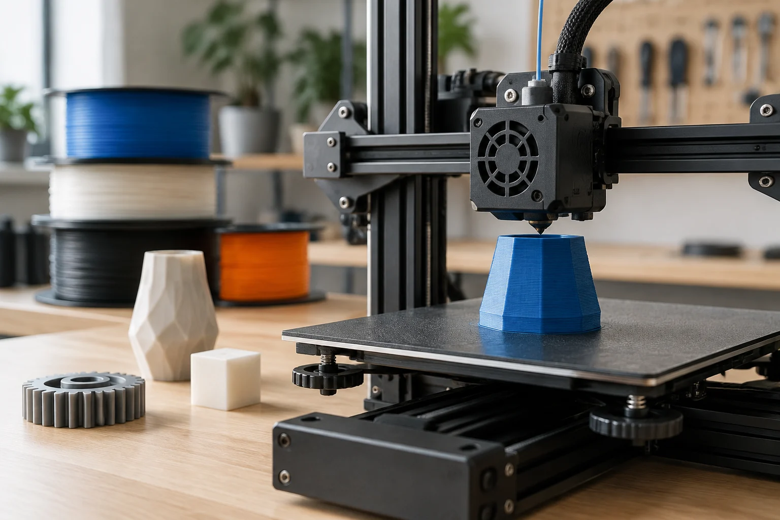
Layer height is the vertical thickness of each layer, not the filament diameter. A thinner layer can show more vertical detail and increase print time; the effects depend on the object and machine. Nozzle diameter is a separate setting that affects the possible extrusion width.
Perimeters, or walls, form the outer shell. Infill occupies part of the interior and can be configured with different densities and patterns, such as lines, grid, or gyroid. These geometries involve trade-offs in material, time, and support for top surfaces; there is no single best pattern for every part, nor a density that guarantees a particular strength on its own.
Print speed refers to movement while material is being deposited. Travel moves the nozzle without extruding material. Retraction pulls filament back during certain travels to help reduce stringing or oozing, but there is no universal retraction distance: it depends on the extruder, material, and profile.
The preview lets you check for suspended areas, which regions receive supports, and how the layers are built. If you change a setting, slice again and review the result: the previous preview may no longer represent the new instructions.
Supports, raft, brim, and skirt are not the same
Supports hold up overhangs or parts that have no material beneath them during printing. A slicer can generate them automatically or allow you to place them manually. Model orientation can also reduce the need for supports, though the geometry and expected finish should be considered.
A raft is a sacrificial base printed beneath the part and removed when printing is complete. A brim is an edge attached to the object’s first layer that increases its contact area with the print surface. Each can help in different situations, but both use material and must be removed afterward.
A skirt is printed around the part without touching it. Depending on the profile, it can help stabilize filament flow and check extrusion before the object begins; it does not increase the part’s contact with the base. In short: raft underneath, brim attached to the outline, skirt separate.
Do not add supports or edges out of habit. Inspect the preview and consider whether the model could be oriented better. After printing, remove structures carefully: they can leave marks, and fragments may fly off as they detach.
Common problems and sensible checks
Warping is the lifting or deformation of a part’s edges. It may relate to material shrinkage, adhesion, or environmental conditions. Check that the surface is prepared as the manufacturer specifies, and review orientation, profile, and first layer; changing one variable at a time makes it easier to understand the effect.
Stringing describes fine strands left between parts of a print. Retraction, temperature, moisture, and travel paths can all have an effect. Make adjustments with the filament and profile in mind rather than applying a universal retraction distance.
Poor adhesion occurs when the first layer does not stick well. Check whether the surface is clean and in suitable condition, and review leveling, nozzle distance, and settings compatible with the material. Do not assume an automatic leveling feature will solve the problem.
Over-extrusion deposits more material than expected; under-extrusion leaves too little, which may appear as gaps or incomplete layers. Sensible checks include the profile, flow, nozzle condition, and filament feed. Review these points according to the equipment instructions, and keep hands away from moving parts and hot surfaces.
Post-processing, safety, and learning resources
Let the part cool before removing it, and use suitable tools for supports or burrs. Parts can have sharp edges; protect your eyes from fragments when detaching supports. When sanding, control dust and follow the safety rules of your workspace.
3D printing can involve hot surfaces, moving parts, and emissions of ultrafine particles and chemicals. NIOSH recommends managing these risks with engineering controls, such as adequate ventilation and controls that capture emissions at their source, alongside workplace rules and any protective equipment required for the task. In a library or educational facility, consult the safety plan and the person responsible for the space before starting.
Uncured resin requires different precautions from filament: avoid skin contact and follow the material safety data sheet and the instructions for washing, curing, and waste management. Do not improvise mixtures or disposal methods. In a makerspace, library, or educational facility, also follow local rules and the instructions of the person responsible for the space.
To learn the workflow, consult the UltiMaker Cura repository and documentation, the PrusaSlicer first-print guide, and the FreeCAD import and export manual. On model repositories such as Printables and Thingiverse, check each listing for the author, exact license, and conditions for adapting or redistributing the model. Permissions vary by model. The Creative Commons license guide explains BY (attribution), SA (sharing adaptations under the specified terms), NC (non-commercial use), and ND (restrictions on sharing adaptations). Downloading a file does not grant permissions beyond those in its license.
Quick-reference table: 3D printing terms
Use this summary as a quick reference. If in doubt, the model listing, printer profile, and material manufacturer’s instructions determine which options apply.
| Term | Brief definition |
|---|---|
| Additive manufacturing | Producing objects by successively adding material from a digital design. |
| FDM/FFF | Printing that deposits melted thermoplastic filament through a nozzle. |
| SLA | A process that hardens liquid resin with a laser. |
| DLP | A process that exposes each layer using a projected image. |
| MSLA | A resin process that uses an LCD screen as a light mask. |
| SLS | A process that sinters powder with a laser. |
| 3D modeling | Creating or modifying a digital representation of a three-dimensional object. |
| CAD | Computer-aided design. |
| STL | A triangular-mesh format used for 3D objects. |
| OBJ | A mesh format that can contain 3D object geometry. |
| 3MF | A 3D printing package that can include geometry and additional data. |
| STEP | A format for exchanging CAD geometry. |
| Slicer | Software that prepares a model and generates printing instructions. |
| G-code | Operating and movement instructions for a machine. |
| Extruder | Mechanism that pushes filament toward the heating assembly. |
| Hotend | Assembly that heats filament before it is deposited. |
| Nozzle | Outlet through which melted material is deposited. |
| Heated bed | A print base that can be heated during the process. |
| Print surface | The area where the part begins and its first layer adheres. |
| X, Y, and Z axes | Coordinates that position deposition in the plane and in height. |
| Bed leveling | Adjustment of the distance between the nozzle and print base. |
| First layer | The first deposited layer, whose adhesion should be checked. |
| Filament | Thread-shaped material used by an FDM/FFF printer. |
| PLA | Common FDM/FFF thermoplastic; properties depend on the use and formulation. |
| PETG | Copolyester used as FDM/FFF filament. |
| ABS | Thermoplastic that may require controlled printing conditions. |
| ASA | Thermoplastic used in FDM/FFF printing; check the specific profile. |
| TPU | Flexible thermoplastic available in different formulations. |
| Nozzle and bed temperatures | Separate thermal settings for melting filament and heating the base. |
| Filament moisture | Absorbed water that can impair extrusion of some materials. |
| Room ventilation | Air renewal and control to manage emissions; distinct from part cooling. |
| Layer height | Vertical thickness of each printed layer. |
| Perimeters | Lines that form a part’s outer walls. |
| Infill | Internal structure configured within a part. |
| Infill pattern | Geometry of the internal material paths. |
| Print speed | Movement speed while material is being deposited. |
| Travel | Nozzle movement without depositing material. |
| Retraction | Pulling filament back during certain travels. |
| Supports | Temporary structures that hold up suspended areas. |
| Raft | Sacrificial base printed beneath the object. |
| Brim | Edge attached to the first layer to increase contact with the base. |
| Skirt | Outline printed around, but separate from, the part. |
| Warping | Lifting or deformation of a part’s edges. |
| Stringing | Fine strands between printed areas during travel moves. |
| Poor adhesion | The first layer does not adhere properly to the surface. |
| Over-extrusion | Depositing more material than the profile expects. |
| Under-extrusion | Depositing too little material, often leaving gaps or incomplete layers. |
| Post-processing | Operations after printing, such as removing supports or sanding. |